Reason for CV carburetor membrane diaphragm:
It allows the use of much larger carburetor throat without the problem of stalling if throttle is opened too quickly. There is also the benefit in altitude compensation. (Atmospheric pressure lifts the diaphragm.)
The slide only moves if the velocity of air can cause vacuum differential in the top chamber. Atmospheric pressure is what moves the slide up by pressure on the bottom of the diaphragm. (The slide has a small hole from venturi to communicate with top chamber.) The top chamber must be air-tight.
Original method of attachment:
Most original slides have plastic or metal rings that clamp the rubber diaphragm tightly. These are manufactured by placing the slide in a fixture for proper reference alignment, and expanding, by use of a press, the top of the slide. This makes an air-tight assembly. Some diaphragms may be attached by the use of rivets. Slides are sold as an assembly ready to install.
Operation of slide:
The slide is raised by vacuum in top chamber. The force to raise the slide is mechanical. A small light spring is used to assist in slide return in case engine is not running and there is no vacuum. If the engine is running, manifold vacuum would draw the slide down, but the communication hole and vacuum in top chamber equalizes this pull.
The Venturi causes a pressure differential in the top chamber with increasing air flow and raises the slide. This force, as an example, on an 80mm diaphragm, would be about 7 pounds at only 1 psi differential. Just calculate the area of the diaphragm. Smaller diaphragms would have less force.
JBM replacement slide attachment:
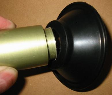
The JBM replacement diaphragm is easy to install and uses no metal or plastic rings. A thick section of rubber molded in the center of the diaphragm is used to replace the old clamping rings. We call this section a "tire". The hole in the tire is about 1 mm smaller than the groove in the slide, so there is some tension on the rubber. This tire can be glued with "super glue" to the metal or plastic slide. Some diaphragms may have a "molded-in" metal plate attached to the slide by rivets.
Material used is important:
JBM uses TSR material that has a very limited amount of stretch. There is no fabric in the rubber to limit stretch. Stretching of the rubber diaphragm would allow the diaphragm to move without lifting the slide, so the throttle will not fully open. Stretching of the rubber would also allow the easy rotation of the slide, as there is no key on the slide to prevent this.
The TSR material we use is also compounded to be "dead" and not bounce. This is to prevent "flutter" of the slide, as the metal slides can be a bit heavy, yet must move quickly.
Easy installation of the tire:
JBM diaphragms are easy to install by removing the metal or plastic clamp rings. Careful installation is very important for long life of the diaphragm. Tires cannot be installed with more than 1 mm of stretch. They also should not be installed over anything that would expand the tire more than 2 mm. All burrs and sharp edges must be removed to prevent nicks in the rubber. No lubricant on the tire should be used other than a small amount of "super glue". (cyanoacrylate adhesive)
Sharp bending of the tire must be avoided as it does not have the stretch for sharp bends. Be sure the tire is warm, and never install in cold temperatures.
The Down sides to this method of attachment:
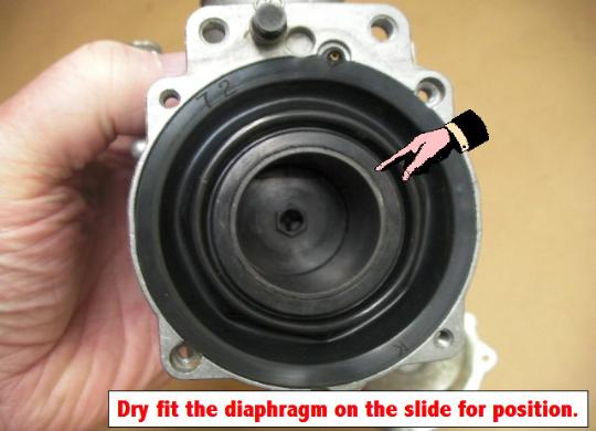
The installer must be sure to position diaphragm correctly on the slide. Some diaphragms we make have key tabs, and this makes installation more difficult, as the diaphragm must first be aligned on the slide so the slide is facing correctly. For this reason diaphragms should be installed one at a time.
Some key tabs in the edge of the diaphragm have a central hole for a small air bleed tube. This may also be sealed with a small O-ring. In some cases removal of the tube might be required as it may not be a functioning feature of the carburetor design.
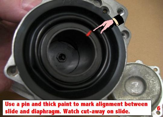
Paint marks should be used for alignment when slide is correctly installed, so it can be easily removed and replaced again. Please don't skip marking your diaphragms.
The tire and diaphragm are chemically resistant, but it is rubber, and can be swollen by chemicals, solvents, and glues. A swollen tire will not hold the slide tightly, so please don't use carburetor cleaners or fuel additives. Contaminating oils cannot be removed, but solvents can sometimes be removed by baking at 200 degrees F. (The original clamping rings do not suffer so much from this, in that swelling of the rubber just made them tighter.)
Normally liquid gasoline never touches the diaphragm, but some carburetors may have a vent to the crankcase that would allow engine oil onto the diaphragm. Synthetic oils could also ruin the diaphragm, so use mineral oil only.
IMPORTANT - Roll the diaphragm:
The final step in assembly should be to roll the diaphragm. The membrane should roll back and forth, and if this is done correctly, they will move very easily. Rolling the diaphragm also makes it much easier to install the top cover.
Air Leaks:
A very small amount of air leaking usually harms nothing, but if you feel you must drill out the air hole in the slide, you best find the leak. To check diaphragms hold them up in a very strong light to find pin holes. Sometimes the original clamping rings, metal or plastic, can be loose and allow an air leak, or rotation of the slide. This can be caused by old rubber shrinking or just age. Drilling out the communication air hole is trying to cure the symptom, and not the problem.
Please don't drill out the air holes.
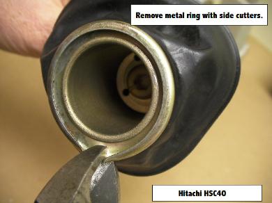
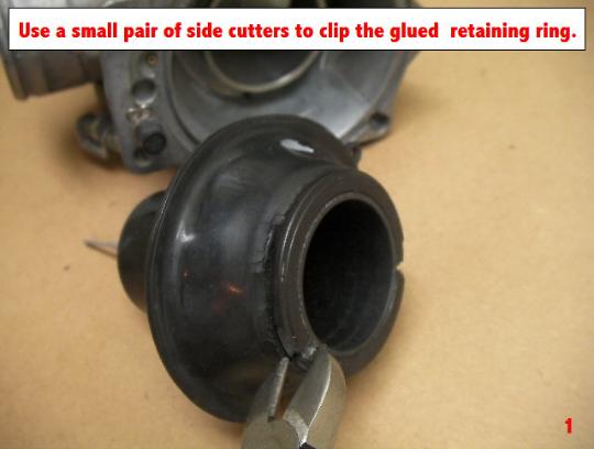
Use small, sharp, side cutters, or jewlers saw. Slides are brittle.